
S5-70WB, S5-PCC, Linux
When we decided to setup our own packet radio network we noticed that there is not a lot of documentation that would provide a beginner with simple to follow instructions how to do it.
We believe there is a need for better documentation of all finished and ongoing projects, so people would know how to use all great things that were created by the radio amateurs from Slovenia. [more]
Introduction
My first equipment was borrowed from my dear friends - S53ZO (Simon Ravnič) and S57NUP (Urban Pirkmajer). S53ZO got me started with WBFM station and antenna. S57NUP also gave me his WBFM station and S5-PCC ISA card (made by S51RM and S53RM) with Manchester modem (made by S53MV). So, I had two WBFM stations, antenna and S5-PCC card. One of the WBFM stations used to work on the same SuperVozelj we were planning on using (S55YMB - see S5 Amateur AX.25 radio network map), so we did not have to worry about fine tuning the station.
I decided to do a search on the web first, convinced, that some documentation with instructions, FAQ, or any other form of discussion about this hardware combination will be found. I am used to search for the documentation first, then, if unsuccessful, I ask friends (I would like to thank S56SAC (Aleš Časar) for his 80 minutes help which killed his telephone battery), and if I am still unsuccessful, I start asking around. I do not want to burden authors of the hardware of software until I am 95% certain I will not be able to solve the problem without their help. With this project I came very close to 85%, but managed to solve it in the last minute. I decided to write step by step instructions targeted at the total beginners as a celebration of my success.
During my initial WWW search I found setup documentation for S5-SCC card, but none for S5-PCC. At first I was a bit confused because of similar names and drivers for two S5-XCC cards (X stands for S or P). The only document describing S5-PCC was found on S53RM S5-PCC home page. It is written in MS Word format. I have created PDF version of the document so Linux users can benefit from it too (it is available only in Slovene language). It was enough to get me started...
About the document
This paper is divided in three parts:
1. Hardware installation
Normally one would decide to setup his or her hardware first. In my configuration I had to setup and insert an S5-PCC card in ISA computer slot, configure S5-70WB to work on the right frequency for connection to local SuperVozelj node in Maribor (S50YMB) and fix an antenna on the appropriate spot facing the SuperVozelj.
First things first. Without antenna (Fig. 1.1) and WBFM station nothing will work, so I decided to set them up first. Cheap RG58 coaxial cable with BNC connector was used to connect the two. The same coaxial cable is used for your local Ethernet connections, so it should be available in first computer or electronics shop in your neighbourhood. It is not the best choice, but it will do just fine. The length of cable should be 17.5 cm * 0.66 * N , where N is natural number.
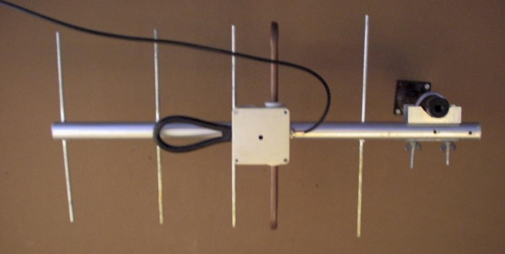
Fig. 1: S53ZOs yagi antenna for 70 cm in my room facing the Pohorje hills
1.1 S5-70WBFM setup
We did not have a lot of work with S5-70WB because it used to work on the same frequency. Nevertheless there are some note worthy remarks.
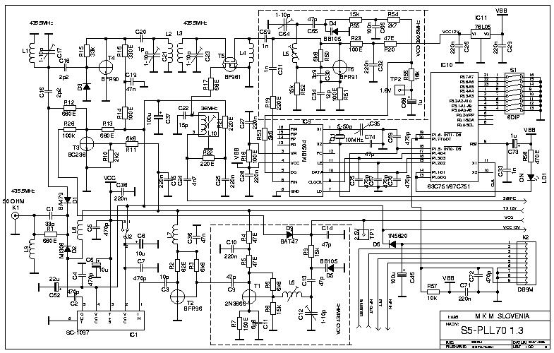 | 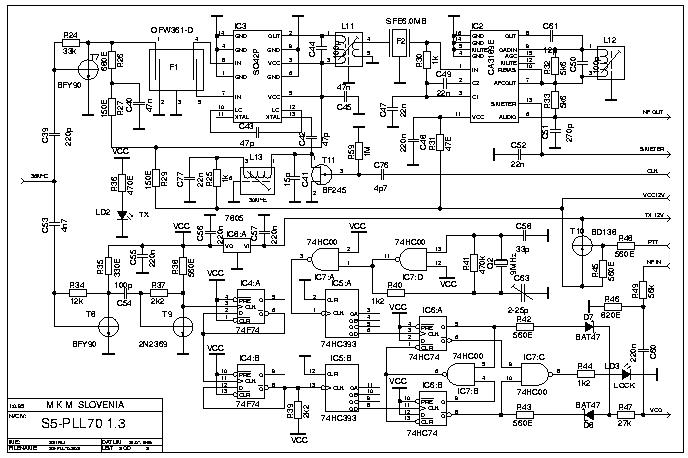 |
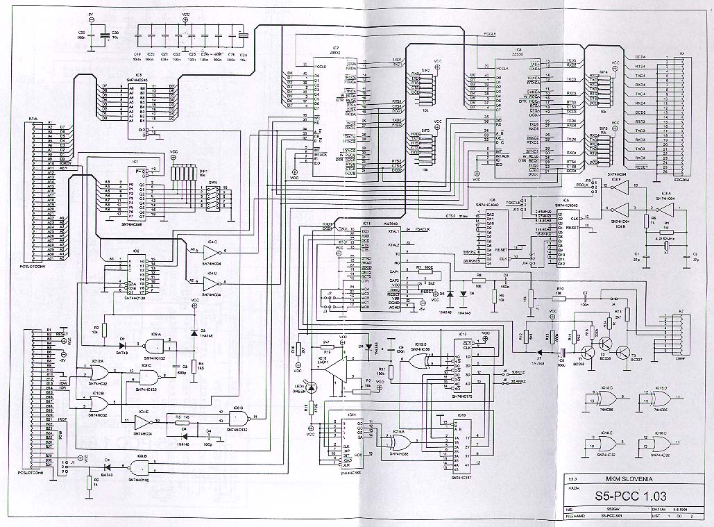
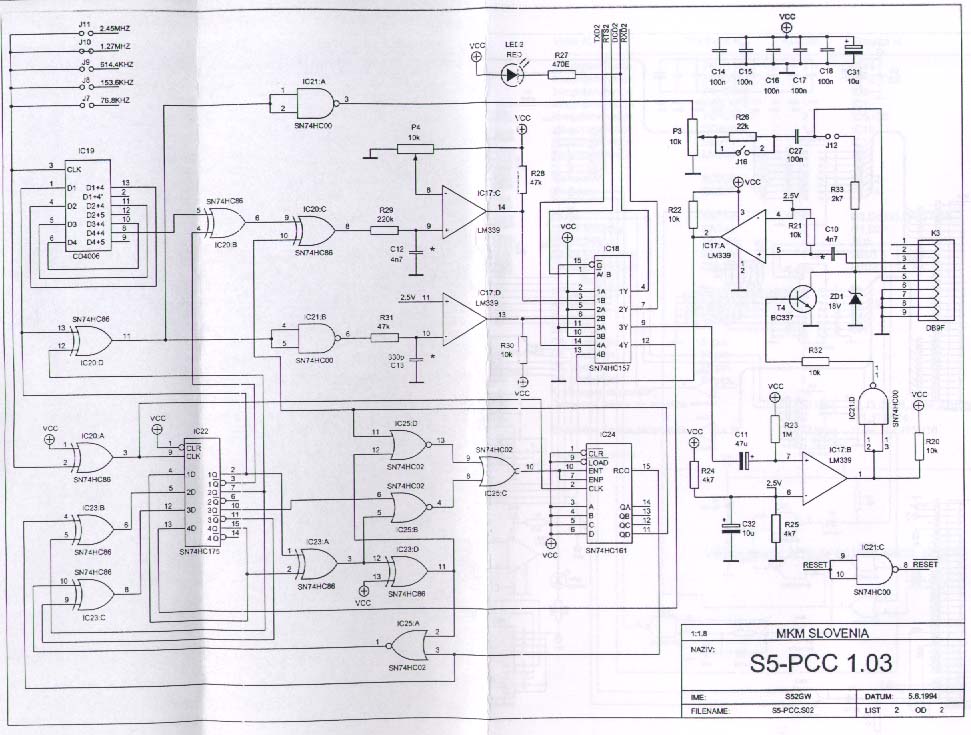
| Figure 1.2: Circuit design 1/2 | Figure 1.3: Circuit design 2/2 |
First thing to do is get the right XTAL for the frequency you are planning to work on - usually local SuperVozelj dictates that. Check S5 Amateur AX.25 radio network map to find closest to your location in Slovenia. SuperVozelj in Maribor (S55YMB) is working with 38.4 kbps on 437,70 MHz (f0).
To calculate which XTAL you need you have to:
- check the value of SFE (on board location) - it should read 5.5, 5.74, 6.0, or 6.5 MHz,
- check the value of XTAL1 (on board location),
- check the value of XTAL2 (on board location),
- based on XTAL1 and XTAL2 values find in table 1.1 your 1st mid frequency (f1).
Table 1.1: S5-WBFM Frequency selection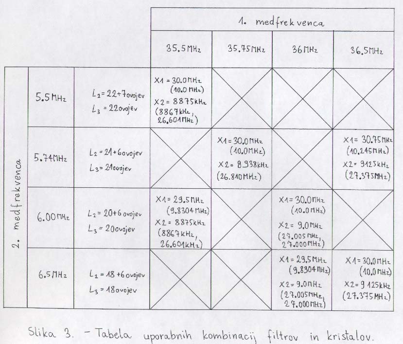
Our configuration: SFE=6 MHz, XTAL1=10 MHz, XTAL2=27 MHz -> f1=36 MHz (Fig. 1.4).
XTAL3 = (f0 - f1)/(5 * 3)
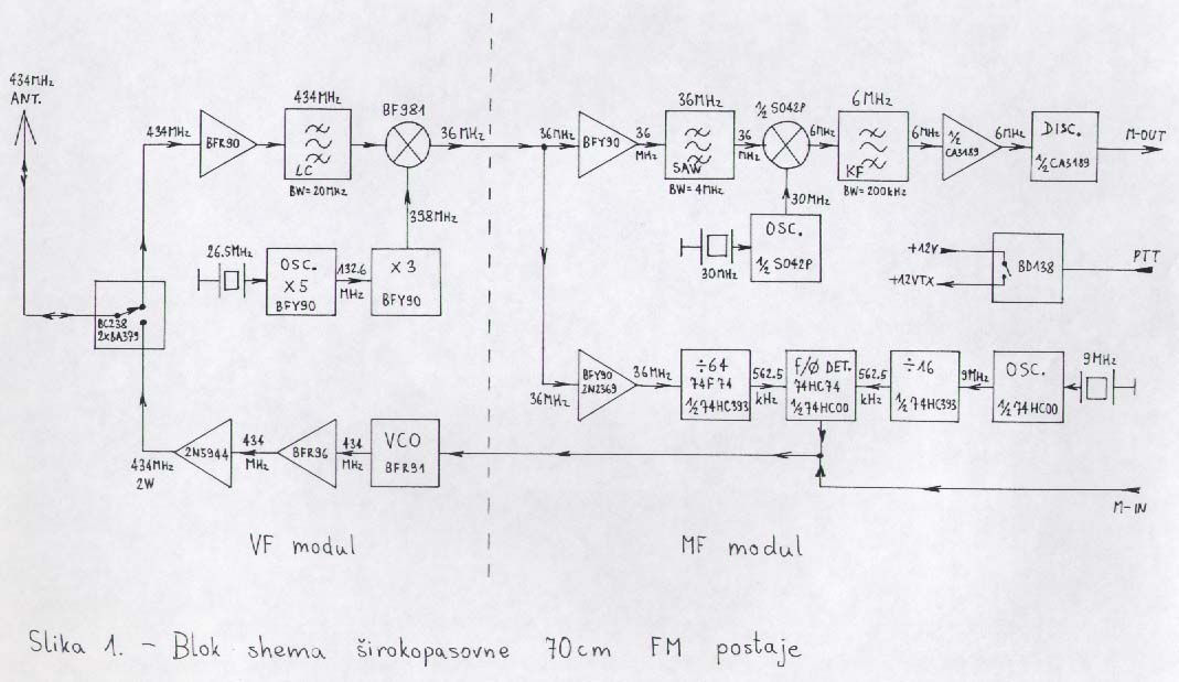
Figure 1.4: S5-WBFM Block Diagram.
One of the stations already had the right XTAL (26.78 MHz), so we did not have to search for it. If your local electronic shop does not have XTAL3, check at your local radio club.
Later on we will discuss how to check if your S5-WBFM works, but first we have to set up S5-PCC interface.
1.2 S5-PCC setup
S5-PCC is USCC compatible. It was developed for those radio amateurs that want to operate with higher throughput. S5-PCC supports speeds from 2400 bps to 76800 bps with Manchester modem, and 300 bps to 1200 bps with FSK modem. S5-PCC components:
- two SCC chips for 4 channels,
- two integrated modems,
- two additional external modems can be connected.
We will focus only on on-board Manchester modem, so we will be using one SCC chip with two channels. Manchester modem is on the second channel.
 |  | 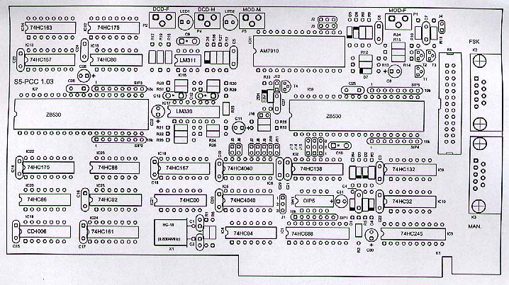 |
| Figure 1.5: Circuit design 1/2 | Figure 1.6: Circuit design 2/2 | Figure 1.7: Component location |
1.2.1 I/O address
First we have to setup the I/O address of the card. This is done through the DIL switches (on board location).
Address can be set to:
- 200H - 260H,
- 280H - 2D0H,
- 300H - 360H.
Use of address 300H is recommended, because it is reserved for prototype cards. Table 1.2 shows the proper switch setup.
| Address | SW1-1 | SW1-2 | SW1-3 | SW1-4 | SW1-5 |
| 210H | off | on | on | on | on |
| 220H | on | off | on | on | on |
| 230H | off | off | on | on | on |
| 240H | on | on | off | on | on |
| 300H | on | on | on | on | off |
| 310H | off | on | on | on | off |
| 320H | on | off | on | on | off |
| 330H | off | off | on | on | off |
| 340H | on | on | off | on | off |
For 300H you should set only SW1-5 (on board location) to off.
1.2.2 IRQ selection
IRQ is selected with J1 (see on board location). We can choose between IRQ5 (jumper must be on 2-3) and IRQ7 (jumper must be on 1-2). We have tested with both IRQs and it worked equally well. Since IRQ 7 is used also by parallel port I would suggest IRQ 5 to be used.
1.2.3 Speed selection
Speed setup is done with jumper selection and proper combination of capacitors.
| Speed | C10 | C12 | C13 |
| 2400 bps | 15n | 68n | 4n7 |
| 4800 bps | 10n | 47n | 2n2 |
| 9600 bps | 10n | 33n | 1n5 |
| 19200 bps | 10n | 10n | 680p |
| 38400 bps | 4n7 | 4n7 | 330p |
| 76800 bps | 2n2 | 2n2 | 220p |
| Speed | J7 | J8 | J9 | J10 | J11 | J13 | J14 | J15 |
| 1200 bps | 1 | 0 | 0 | 0 | 0 | 1-2 | 1-2 | 1-2 |
| 2400 bps | 0 | 1 | 0 | 0 | 0 | 1-2 | 1-2 | 1-2 |
| 4800 bps | / | / | / | / | / | / | / | / |
| 9600 bps | 0 | 0 | 1 | 0 | 0 | 1-2 | 1-2 | 1-2 |
| 19200 bps | 0 | 0 | 0 | 1 | 0 | 1-2 | 1-2 | 1-2 |
| 38400 bps | 0 | 0 | 0 | 0 | 1 | 1-2 | 1-2 | 1-2 |
| 76800 bps | / | / | / | / | / | / | / | / |
| Speed | J7 | J8 | J9 | J10 | J11 | J13 | J14 | J15 |
| 1200 bps | / | / | / | / | / | / | / | / |
| 2400 bps | 1 | 0 | 0 | 0 | 0 | 2-3 | 2-3 | * |
| 4800 bps | 0 | 1 | 0 | 0 | 0 | 2-3 | 2-3 | * |
| 9600 bps | / | / | / | / | / | / | / | / |
| 19200 bps | 0 | 0 | 0 | 1 | 0 | 1-2 | 1-2 | 1-2 |
| 38400 bps | 0 | 0 | 0 | 0 | 1 | 2-3 | 2-3 | * |
| 76800 bps | 0 | 0 | 0 | 0 | 1 | 2-3 | 2-3 | 1-2 |
1.2.4 Additional remarks
Our S5-PCC has 9.8304 MHz XTAL, but we were not aware of that at the beginning. We were not able to read the value of XTAL, because of its on-board orientation. Because we knew that S57NUP used to work on 38.4 kbps we have figured out that installed XTAL works on 9830400 Hz from jumper selections. We have written it down on small peace of paper and forgot about it by the time of Z8530 (on board serial chip) setup. Because of misplaced peace of paper we have set up the Linux scc driver (/etc/z8530drv.conf) to the default pclock 4915200 instead of pclock 9830400. Nothing worked, of course!
Be sure to check the value of XTAL (see the on-board location) before the setup of scc driver!
We found capacitors C10, C12, and C13 (see the on-board location) to be set for the speed of 76800 bps - we learned that S57NUP used to work on that speed in Ljubljana, but changed it to 38400 bps when he moved to Celje. A friend who fixed his board obviously forgot to change capacitors. As it turns out that was not a big deal. S5-PCC works just fine with both capacitor groups.
Be sure to:
- set I/O address,
- set IRQ,
- check value of XTAL,
- set modulation level with P3 (see the on-board location). For start just set it to the middle position (form my experience modulation is not critical),
- set DCD (Data Carrier Detect) level with P4 (see the on-board location).
DCD is a signal indicating the presence of data on the communication channel. DCD signal is used to hold-off the transmitter when the channel is occupied. Some TNCs and modems employ a "DCD" that simply indicates the presence of a RF carrier or noise energy on the channel rather than true Data Carrier Detect. That is exactly what S5-PCC is doing - detecting activity on the channel. You can set the thresh hold with P4, so main processor does not get swept with IRQs. Set it to max value - all the way to the right. The LED2 (see the on-board location) should light up if signal or noise is detected. When set to the maximum value light should be constantly on. If not, you should check your antenna and cable connections. Now slowly start reducing the value of DCD until LED2 lights up only when there is some activity on the channel. How do you know that there is any activity? At this point only with the help of the friend who is able to generate some traffic on the channel. You can compare the results over the phone or alternate Internet connection. If you do not have a friend who could help you - we doubt that -, you will be able to do it by yourself later on if everything goes well. DCD configuration is very important for optimal performance! We will talk more about it in thetroubleshooting section.
That concludes the hardware part of the setup.
2. Software setup
Any hardware device has to be supported by software drivers to work with the operating system. We will describe all necessary steps for the set up of S5-PCC, AX.25 kernel support and TCP/IP networking over AX.25.
Description of all protocols used in packet radio and installation procedures can be found in AX25-HOWTO. We will provide only installation steps that are necessary to get TCP/IP up and running.
Five steps in software setup:
S5-PCC is compatible with USCC (Z8530) BAYCOM card. Z8530 chip cards use universal Z8530 SCC driver.
2.1 Kernel setup
Because of the necessary changes you will most probably have to compile your Linux kernel. Do not get scared. There is nothing to it, you just have to be a little careful. If this is your first time we suggest reading the The Linux Kernel online book and Linux Kernel HOWTO.
2.1.1 Step by step instructions
Change directory to your Linux kernel source - usually /usr/src/linux. If the directory does not exist you do not have Linux kernel sources installed. Install it from your distribution CD or get it from your closest ftp or web site.
If you are running X windows do a make xconfig for nice Tk/Tcl interface, if not, you can do a make menuconfig. If this is the first time you are compiling kernel on your computer be sure to set up all necessary drivers for the other hardware being used (hard disks, CD-ROM, Ethernet card, printer, file systems, PPP, etc.). Be careful with that! We recommend keeping the working kernel as a back up, if something goes wrong. Detailed description of kernel compilation and precaution steps needed is out of the scope of this document. From now on we will discus only steps needed for AX.25 and S5-PCC support. We assume your TCP/IP is already set up correctly. If you have problems setting up TCP/IP we suggest reading Linux Network Administration Guide.
Getting on with the setup ... be sure to select:
- Amateur Radio support,
- Z8530 SCC driver.
Do a make dep and make bzImage to compile the kernel. You can decide to use modules for scc and AX.25 support. They can save you a couple of reboots while setting up S5-PCC, but require some additional work which we will described in detail later on. That can be quite handy and can speed up the set up of your configuration. We recommend that only to more experienced users. If you have never heard about lsmod, insmod, and rmmod we do not recommend using modules - they might confuse you. Our goal is to get your packet radio working as soon as possible. If you decide to use them, be sure to do make modules and make modules_install. Next, copy the new Linux image to the /boot directory (or any other directory your distribution is using). You can do that with:
cp /usr/src/linux/arch/i386/boot/bzImage /boot/vmlinuz_ax25
Edit /etc/lilo.conf and change following lines:
default=Linux_AX25 image=/boot/vmlinuz label=Linux read-only image=/boot/vmlinuz_ax25 label=Linux_AX25 read-only
Keep the old Linux kernel - in our case /boot/vmlinuz - as a back up if something goes wrong! After every /etc/lilo.conf change you have to run /sbin/lilo to apply the changes. Command should produce:
Added Linux Added Linux_AX25 *
If you have problems with LILO we recommend reading LILO mini HOWTO.
After successful kernel compilation we have to reboot the computer so new kernel can get loaded. When all goes well (hopefully the first time) we are ready to proceed.
Before moving to S5-PCC setup make sure following software packages are installed:
- z8530-utils2,
- x25-apps,
- ax25-tools,
- libax25.
2.2 S5-PCC drivers setup
If you decided to use modules you have to load drivers after the reboot with insmod ax25; insmod scc. If everything goes well lsmod should list both modules:
Module Size Used by scc 17632 0 (unused) ax25 38080 0 [scc]
If you use modules or not dmesg should include a printout similar to this:
NET4: G4KLX/GW4PTS AX.25 for Linux. Version 0.37 for Linux NET4.0 Z8530 SCC driver version 3.0.dl1bke (experimental) by DL1BKE Copyright 1993,1998 Joerg Reuter DL1BKE (jreuter@poboxes.com) scc0: data port = 0x300 control port = 0x304 -- found scc1: data port = 0x301 control port = 0x305 -- found Init Z8530 driver: 2 channels, IRQ 5
If the AX.25 kernel code or S5-PCC card is not recognised there is something wrong with your kernel setup. Please check everything again.
For our computer to use S5-PCC we have to initialise it with sccinit. It is included in package z8530-utils2. Make sure it is installed on your system. Setup file for sccinit is located in /etc/z8530drv.conf. Check if it is setup correctly. The file is divided in three parts: hardware section, software section, and Level 1 parameters.
2.2.1 Hardware section
This is the most important part of the file. Changes in this part of configuration file can not be applied without the reboot of the system or reload of modules. The right configuration for our hardware is presented with following lines:
# Hardware section # # SCC chip 1 # chip 1 data_a 0x300 # data port A ctrl_a 0x304 # control port A data_b 0x301 # data port B ctrl_b 0x305 # control port B irq 5 # IRQ No. 5 pclock 9830400 # clock # pclock 4915200 # default clock board BAYCOM # hardware type escc no # enhanced SCC chip? (8580/85180/85280) vector no # latch for interrupt vector special no # address of special function register option 0 # option to set via sfr
If you decide to use another I/O address or IRQ than suggested, make sure to set it right here. Double check all parameters! If this part is not right, nothing will work! Be sure to check the value of XTAL and set correct pclock.
2.2.2 Software section
In software section new devices are defined. Each Z8530 chip has two pairs of data and control ports. Manchester modem is located at second pair (data_b, ctrl_b). Device (/dev/scc1) that represents interface to the channel is defined with:
# Definition of /dev/scc1 # device /dev/scc1 # # speed 38400 # 38400 baud clock dpll # clock source: use the dpll mode nrzi # normal NRZI operation
All, but clock and mode parameters from here on can be changed with sccparam program, so we do not have to reboot the computer or reload modules for changes to take effect. Examples will be provided.
2.2.3 Level 1 parameters
In the last part of the configuration file we have to define Level 1 parameters. Most of them dictate the behaviour of S5-PCC on the channel.
# # Level 1 parameters # txdelay 10 persist 64 slot 20 tail 5 fulldup 0 wait 5 min 3 maxkey 20 idle 3 maxdef 120 group 0
| Parameter | Description |
| txdelay | The delay (in units of 10ms) after keying of the transmitter, until the first byte is sent. This is usually called "TXDELAY" in a TNC. When 0 is specified, the driver will just wait until the CTS signal is asserted. This assumes the presence of a timer or other circuitry in the MODEM and/or transmitter, that asserts CTS when the transmitter is ready for data. A normal value of this parameter is 30-36. Example: sccparam scc1 txd 10 |
| persist | This is the probability that the transmitter will be keyed when the channel is found to be free. It is a value from 0 to 255, and the probability is (value+1)/256. The value should be somewhere near 50-60, and should be lowered when the channel is used more heavily. Example: sccparam scc1 persist 64 |
| slot | This is the time between samples of the channel. It is expressed in units of 10ms. 50 ms seems to be a good value. Example: sccparam scc1 slot 5 |
| tail | The time the transmitter will remain keyed after the last byte of a packet has been transferred to the SCC. This is necessary because the FCS (Frame Check Sequence) (16 bits) and a flag (8 bits) still have to leave the SCC before the transmitter is keyed down. The value depends on the baud rate selected. For 38400 baud 10 ms should be enough even in extremely bad conditions. The value of this parameter is in 10ms units. Example: sccparam scc1 tail 1 |
| fulldup | The full-duplex mode switch. This can be one of the following values: 0: The interface will operate in CSMA mode (the normal half-duplex packet radio operation) Example: sccparam scc1 fulldup off |
| wait | The initial wait time before any transmit attempt, after the frame has been queue for transmit. This is the length of the first slot in CSMA mode. In full-duplex modes it is set to 0 for maximum performance. The value of this parameter is in 10ms units. Example: sccparam scc1 wait 1 |
| maxkey | The maximal time the transmitter will be keyed to send packets, in seconds. This can be useful on busy CSMA channels, to avoid "getting a bad reputation" when you are generating a lot of traffic. After the specified time has elapsed, no new frame will be started. Instead, the trans- mitter will be switched off for a specified time (parameter min), and then the selected algorithm for keyup will be started again. The value 0 as well as "off" will disable this feature, and allow infinite transmission time. Example: sccparam scc1 maxk 20 |
| idle | This parameter specifies the maximum idle time in full-duplex 2 mode, in seconds. When no frames have been sent for this time, the transmitter will be keyed down. A value of 0 is has same result as the full-duplex mode 1. This parameter can be disabled. Example: sccparam scc1 idle off # transmit forever |
| maxdef | This is the maximum time (in seconds) to wait for a free channel to send. When this timer expires the transmitter will be keyed IMMEDIATELY. If you love to get trouble with other users you should set this to a very low value ;-) Example: sccparam scc1 maxdefer 120 |
| group | It is possible to build special radio equipment to use more than one frequency on the same bad, e.g. using several receivers and only one transmitter that can be switched between frequencies. Since we are not using that setup, we have to set it to 0. |
| txoff | When this parameter has the value 0, the transmission of packets is enable. Otherwise it is disabled. Example: sccparam scc1 txoff off |
| softdcd | Use a software dcd instead of the real one... Useful for a very slow squelch. Example: sccparam scc1 soft on |
If you have problems at this stage, you will find detailed description of procedures in /usr/share/doc/z8530-utils2/scc_eng.doc (in Debian 2.2 distribution). We advise you to read the provided documentation even if everything works fine in the first try.
When everything is set up we should reboot the computer or reload the scc module (rmmod scc; insmod scc) and initiate the card with sccinit.
That concludes S5-PCC driver installation.
2.2.4 Additional remarks
If you decided to use modules you have to make sure they will get loaded every time you boot the computer. For automatic module loading you have two options:
- /etc/modules
You can add following lines to
/etc/modules:#Packet-radio ax25 scc - start them from one of the scripts in
/etc/init.ddirectory during the boot of the computer.
We have to make sure sccinit gets run, too. We recommend second option - we can take care of all initialisation steps in one file - /etc/init.d/s5pccinit. It has to appear in the system rc directory. You can check /etc/fstab to see which system rc directory you are using. Look for line similar to:
# Boot-time system configuration/initialisation script. si::sysinit:/etc/init.d/rcS
It tells us that /etc/init.d/rcS will be run on system startup. If you take a peek in it, we can find the system rc directory. Search for the line similar to:
for i in /etc/rcS.d/S??*
In Debian 2.2 distribution system rc directory is located in /etc/rcS.d. It looks a bit complicated, doesn't it? Do not fear, we will describe the procedure step by step.
We suggest to put s5pccinit configuration script in /etc/init.d and make a symbolic link to it from /etc/rcS.d.
Instructions:
- create file
/etc/init.d/s5pccinit:#!/bin/sh # # start/stop networking daemons. echo -n "S5PCC interface:" s5pcc_on () { insmod ax25 insmod scc sccinit } s5pcc_down () { rmmod scc rmmod ax25 } case "$1" in start) echo "starting..." s5pcc_on echo "done." ;; stop) echo -n "stopping..." s5pcc_down echo "done." ;; restart) echo -n "restarting..." s5pcc_down s5pcc_on echo "done." ;; *) echo "Usage: s5pccinit {start|stop|restart}" exit 1 ;; esac exit 0If you compiled scc and ax25 support in your kernel, so you are not using modules, you have to skip all lines that includeinsmodorrmmod. - cd to
/etc/rcS.d, - make a symbolic link:
ln -s ../inid.d/s5pccinit S25s5pccinit
On your next reboot everything will get setup automagically. If you are using modules, /etc/inid.d/s5pccinit can be used for scc parameter testing - only for ones that need scc module to be reloaded. Here the advantage of module usage becomes obvious. If you decide to change Hardware or Software section parameters in /etc/z8530drv.conf you do not have to reboot the computer - simple /etc/inid.d/s5pccinit restart will do the job. All your editors, web browsers etc. can stay open and help you set up the computer. We believe modules are worth additional effort.
You can check current configuration of S5-PCC drivers with sccstat scc1 and change it with sccparam program (see examples in Table 2.1).
Read more about it in /usr/src/linux/Documentation/networking/z8530drv.txt.
2.3 AX.25 setup
As you probably already know we use AX.25 as level 2 protocol in amateur digital radio communications.
From AX.25 HOWTO:
The AX.25 protocol offers both connected and connection-less modes of operation, and is used either by itself for point-point links, or to carry other protocols such as TCP/IP and NetRom.
It is similar to X.25 level 2 in structure, with some extensions to make it more useful in the amateur radio environment.
We will focus on AX.25 as carrier of TCP/IP datagrams. Make sure you installed software packages:
- x25-apps,
- ax25-tools,
- libax25.
2.3.1 Port configuration
Ports are used for communication with physical devices. Each port represents one physical device. Configuration of AX25 ports is stored in /etc/ax25/axports. Call sign for each port should be unique. If you own only one S5-WBFM your configuration file should look something like this:
# /etc/ax25/axports # # name callsign speed paclen window description # scc1 S56WBV-0 38400 512 7 S5-PCC with WBFM
Although you can freely choose the name of the port, we recommend setting it to the device name of your physical interface - in our case scc1. Do not forget to change a call sign to your own! "-0" part is called Secondary Station Identifier (SSID). You can choose it freely between 0-15, but have to notify system operator of your gateway so he/she can set AX.25 routing tables. SSID enables Radio Amateur operator to have more than one packet radio station and use the same call sign.
2.3.2 AX.25 parameters
Additional AX.25 parameters can be set through /proc file system that represents interface to Linux kernel. With simple echo commands we can set some additional parameters (see Table 2.2). Example:
/bin/echo -n 10 > /proc/sys/net/ax25/scc1/maximum_retry_count
| FileName | Meaning | Values | Default |
| ip_default_mode | IP Default Mode: Datagram (DG) mode or Virtual Circuit (VC) mode. With VC mode set, AX.25 provides a reliable channel. It takes care of retransmition of bad frames. When DG mode is enabled it is up to the level 3 protocol or application. TCP provides reliable channel to the Internet applications. | 0=DG 1=VC | 0 |
| ax25_default_mode | AX.25 Default Mode | 0=Normal 1=Extended | 0 |
| backoff_type | Backoff | 0=Linear 1=Exponential | 1 |
| connect_mode | Connected Mode | 0=No 1=Yes | 1 |
| standard_window_size | The maximum number of unacknowledged transmitted frames. | 1 <= N <= 7 | 2 |
| extended_window_size | Extended Window | 1 <= N <= 63 | 32 |
| t1_timeout | How long to wait before retransmitting an unacknowledged frame. This time should never be shorter than the maximum frame sequence transmission time - t1_timeout=standard_window_size*(maximum_packet_lengthi+72)*8/38400. For good connections standard_window_size is ussualy set to 7, so equation returns recommended value of 500 ms (2 s for the hacked version of AX.25 with maximum_packet_length set to 1500 B). | 1s <= N <= 30s | 10s |
| t2_timeout | The minimum amount of time to wait for another frame to be received before transmitting an acknowledgement. It should be longer than the time needed to accept the longest possible frame. For 38.4 kb/s prefered time would be 70 ms - t2_timeout=(maximum_packet_lengthi+72)*8/38400. If you are using "hacked" AX.25 with maximum_packet_length set to 1500 B, time should be set to 300 ms. | 1s <= N <= 20s | 3s |
| t3_timeout | The period of time we wait between sending a check that the link is still active. It should be approximately "10*t1_timeout", which is for 38.4 kb/s 2.5 s (20 s for maximum_packet_length set to 1500). | 0s <= N <= 3600s | 300s |
| idle_timeout | The period of time a connection can be idle before we close it down. | 0m <= N | 20m |
| maximum_retry_count | How many times to retransmit a frame before assuming the connection has failed. | 1 <= N <= 31 | 10 |
| maximum_packet_length | AX.25 Frame Length | 1 <= N <= 512 | 256 |
Recommended values that work fine can be set with a set of echo commands:
echo -n 2 > /proc/sys/net/ax25/scc1/t1_timeout echo -n 1 > /proc/sys/net/ax25/scc1/t2_timeout echo -n 0 > /proc/sys/net/ax25/scc1/idle_timeout echo -n 10 > /proc/sys/net/ax25/scc1/maximum_retry_count echo -n 0 > /proc/sys/net/ax25/scc1/ax25_default_mode echo -n 376 > /proc/sys/net/ax25/scc1/maximum_packet_length
2.3.3 AX.25 routing
Routing information defines how packages will reach our gateway. We can choose between two types of connection: virtual circuit or datagram mode (Table 2.2).
Setup of AX.25 routing is done with axparms and arp. Demonstrated usage will setup connection to the S50DXX via S55YMB on its third channel. It is important to know on which channel your gateway is working. Just ask gateway administrator or check published SuperVozelj data. Datagram mode will be used.
maximus$ /usr/sbin/axparms -route add scc1 S50DXX S55YMB-3 -ipmode D maximus$ /usr/sbin/arp -H ax25 -i scc1 -s 164.8.73.16 S50DXX
If we would change S50DXX with default in axparms command line it would be used for all outgoing AX.25 connections not associated with any other route.
You can check your current setup with cat /proc/net/ax25_route.
2.3.4 SCC1 Interface setup
To use TCP/IP over AX.25, interface to the /dev/scc1 has to be setup. Following code will do the job:
ifconfig scc1 164.8.73.16 netmask 255.255.255.255 broadcast 164.8.73.16 arp up ifconfig scc1 hw ax25 S56WBV mtu 296
Make sure to replace 164.8.73.16 with your IP address. Do not forget to change call sign, too. We can check current interface configuration with ifconfig scc1.
scc1 Link encap:AMPR AX.25 HWaddr S56WBV inet addr:164.8.73.166 Mask:255.255.255.0 UP RUNNING MTU:296 Metric:1 RX packets:0 errors:0 dropped:0 overruns:0 frame:0 TX packets:0 errors:0 dropped:0 overruns:0 carrier:0 collisions:0 txqueuelen:16
Wondering why we decided to set Maximum Transfer Unit (MTU) to 296?
MTU = MSS (Maximum Segment Size) + 40 Bytes of TCP/IP headers
We have chosen to use 256 bytes for our maximum data segment size. All packets that will be larger than this will be segmented by IP layer. Now we can also explain the strange value of maximum_packet_length. AX.25 adds additional 80 Bytes of headers to our data segment size.
maximum_packet_length = MTU + 80 Bytes of AX.25 overhead (headers and trailers) = 376 Bytes
We can safely set maximum_packet_length to larger number, but there will not be any packages that would exceed that value. Linux AX.25 implementation defines 512 Bytes as maximum value for maximum_packet_length.
Let us stop for a minute and think about that. If we use FTP to transfer files, we will use MSS most of the time of connection. In that mode of operation data will represent only(256/maximum_packet_length)*100=68.1% of transferred information. Our link is actually working on 26140 bps. Maximum theoretical transfer is less than 3.268 kBps. We have to take into account that we are working in half duplex mode, we stop for 3 seconds on every transmition longer than 20 seconds, and that other users are using the channel. Speeds little higher than 2 kBps are theoretical limit when optimal conditions are available. If your antenna is setup correctly and you have a good connection to SuperVozelj, you will achieve that speed with our recommended setup.
Most of our "on-line" time we browse the Web. Do you think that browsing requires 256 Bytes long data segments? Well, it does not! Figure 2.1 shows statistical data from NASA Ames Internet Exchange.
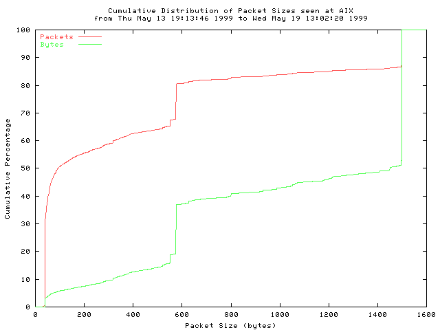
Fig. 2.1: Distribution of IP packet sizes seen at the NASA Ames Internet Exchange.
Statistics for the underlying packet length distribution:
Mean: 413 bytes, Standard Deviation: 509 bytes
Median: 93 bytes, Percentiles: 5th 40 bytes, 25th 40 bytes, 75th 576 bytes, 95th 1500 bytes
Number of Observations: 127 million packets [127710031 packets]
More than 50% of all IP packages is smaller than 296 Bytes. Median value is 93 bytes. Recalculating the line use gives us: (93/(93 + 40 + 80))*100=43.7%. Only 43.7% of our bandwidth is used for transfer of data segments - less than 2100 Bps (do not forget about other users and half-duplex operation). Enough of theory, let us move on with the setup ...
2.3.5 IP routing
Routing of packets is essential if we want to talk to the rest of the TCP/IP world. A new route that will tell the Linux kernel where to send all IP datagrams has to be set up.
Command:
route add default gw 44.150.72.1 dev scc1
should do the job. Check current routing setup with route.
Kernel IP routing table Destination Gateway Genmask Flags Metric Ref Use Iface localnet * 255.255.255.0 U 0 0 0 eth0 164.8.73.0 * 255.255.255.0 U 0 0 0 scc1 default 44.150.72.1 0.0.0.0 UG 0 0 0 scc1
That concludes our AX.25 setup. All parts of our hardware and software are now up and running. Next, we have to check if that is actually true.
2.3.6 Additional remarks
If you decided to use modules you already know how to write boot scripts. Since we already discussed how to do it while setting up S5-PCC card, we will provide just quick installation steps:
- create file
/etc/init.d/ham_networking:#!/bin/sh # # start/stop networking daemons. ham_on () { /sbin/ifconfig scc1 164.8.73.16 netmask 255.255.255.0 /sbin/ifconfig broadcast 164.8.73.255 arp up /sbin/ifconfig scc1 hw ax25 S56WBV mtu 296 /sbin/route add default gw 44.150.72.1 dev scc1 /usr/sbin/axparms -route add scc1 S50DXX S55YMB-2 -ipmode d /usr/sbin/axparms -assoc policy deny /usr/sbin/axparms -assoc S56WBV bvla /usr/sbin/arp -H ax25 -i scc1 -s 44.150.72.1 S50DXX /bin/echo -n 600 > /proc/sys/net/ax25/scc1/t1_timeout /bin/echo -n 65 > /proc/sys/net/ax25/scc1/t2_timeout /bin/echo -n 0 > /proc/sys/net/ax25/scc1/idle_timeout /bin/echo -n 10 > /proc/sys/net/ax25/scc1/maximum_retry_count /bin/echo -n 0 > /proc/sys/net/ax25/scc1/ax25_default_mode /bin/echo -n 376 > /proc/sys/net/ax25/scc1/maximum_packet_length } ham_down () { /sbin/ifconfig scc1 down } case "$1" in start) echo "Configuring Amateur Radio interfaces:" ham_on echo -n "done" ;; stop) echo -n "Deconfiguring Amateur Radio interfaces:" ham_down echo -n "done." ;; restart) echo -n "Reconfiguring Amateur Radio interfaces:" ham_down ham_on echo -n "done." ;; *) echo "Usage: ham_networking {start|stop|restart}" exit 1 ;; esac exit 0 - cd to
/etc/rcS.d - make a symbolic link:
ln -s ../inid.d/ham_networking S41ham_networking
On your next reboot everything will get setup automatically. You can also use /etc/inid.d/ham_networking for starting, stopping or restarting packet radio networking.
If you are using modules and you change your hardware scc parameters, everything can be restarted with:
maximus# s5sccinit stop; ham_networking restart; s5sccinit start
It will work just fine even if you are connected to your computer over packet radio network.
Troubleshooting
By now your packet radio network should work just fine. If not, we recommend checking all setup steps again. If it still does not work or you do not know how to check if everything works well this is the right section to read.
Checking hardware and software setup
When your finish with your hardware and software setup the time has come to verify the quality of your connection. First we have to check if the connection works at all. The best thing to do first is to listen to AX.25 channel to see if we are receiving any data at all.
As we already mentioned in S5-PCC setup, setup of DCD level is extremely important! DCD level setup is very sensitive. First set it to the maximum value (all the way to the right side), then start reducing it until LED2 lights up only then there is traffic on the channel. If there is no traffic we will have to generate some.
Before the traffic generation we have to check if our hardware is detected by drivers and if it is setup correctly:
dmesgshould should include a printout similar to this:NET4: G4KLX/GW4PTS AX.25 for Linux. Version 0.37 for Linux NET4.0 Z8530 SCC driver version 3.0.dl1bke (experimental) by DL1BKE Copyright 1993,1998 Joerg Reuter DL1BKE (jreuter@poboxes.com) scc0: data port = 0x300 control port = 0x304 -- found scc1: data port = 0x301 control port = 0x305 -- found Init Z8530 driver: 2 channels, IRQ 5If you do not find mentioned lines something is wrong with your kernel setup. Check if you have included all necessary drivers. We discuss kernel setup in a Software setupsection. If you decided to use moduleslsmodshould include lines similar to:Module Size Used by scc 17056 1 ax25 32384 0 [scc]sccstat scc1will display current S5-PCC setup:Parameters: speed : 38400 baud txdelay : 2 persist : 64 slottime : 5 txtail : 1 fulldup : 0 waittime : 1 mintime : 3 sec maxkeyup : 20 sec idletime : 3 sec maxdefer : 60 sec group : 0x00 txoff : off softdcd : off Status: HDLC Z8530 Interrupts Buffers ----------------------------------------------------------------------- Sent : 346 RxOver : 0 RxInts : 308882 Size : 384 Received : 1389 TxUnder: 0 TxInts : 24721 NoSpace : 0 RxErrors : 871 ExInts : 8161 TxErrors : 1 SpInts : 1678 Tx State : idleThe errors in RX line are normal. Be sure to set DCD level in a position where successfully received packets outnumber the errors on the channel. You can set most of the parameters of scc driver withsccparam scc1 name value. Example:sccparam scc1 txdelay 2. Values are in units of 10ms if not otherwise stated.ifconfig scc1should display:scc1 Link encap:AMPR AX.25 HWaddr S56WBV inet addr:164.8.73.16 Mask:255.255.255.0 UP RUNNING MTU:296 Metric:1 RX packets:1360 errors:807 dropped:0 overruns:0 frame:0 TX packets:336 errors:2 dropped:0 overruns:0 carrier:0 collisions:0 txqueuelen:16The errors in RX line are normal. Be sure to set DCD level in a position where successfully received packets outnumber the errors on the channel. Be sure to set MTU to the right value.route -nshould display:Kernel IP routing table Destination Gateway Genmask Flags Metric Ref Use Iface 192.168.22.0 0.0.0.0 255.255.255.0 U 0 0 0 eth0 164.8.73.0 0.0.0.0 255.255.255.0 U 0 0 0 scc1 0.0.0.0 164.8.73.16 0.0.0.0 UG 0 0 0 scc1Double check if you have specified the window parameter of the route command. If not, correct theham_networkingscript to include:/sbin/route add default gw 164.8.73.16 window 32768 dev scc1If window parameter is not set you will be losing a lot of packets. Seeman routeand RFC 1122 for detailed description.
If all checks out fine, we are ready to proceed.
Checking the connection
In one terminal window log in as root (the super user) and start listening to AX.25 channel with
listen -a -t
All traffic on channel should be nicely seen:
scc1: fm S56SJS-1 to S55YMS ctl RR5v 15:17:05 scc1: fm S55YMB-3 to S56VDI-1 ctl RR1v 15:17:08 scc1: fm S55YMB-3 to S56VDI-1 ctl I13^ pid=F0(Text) len 33 15:17:09 0000 Cannot get directory properties.. scc1: fm S55YMB-3 to S56VDI-1 ctl I14^ pid=F0(Text) len 156 15:17:10 0000 Current directory : /home/users/ftp/pub/users/9a3ux.ZGYAPP:9A0TC 0040 P-2 Node cmd:.!,?,B,C,D,F,H,I,IRC,L,MH,N,PI,P,R,S,TA,T,U,HOME,DI 0080 R,FIND,CD,LAST,YGET,YPUT ->. scc1: fm S50DXX to S56WBV via S55YMB-2* ctl UI^ pid=CC(IP) len 68 15:17:28 IP: len 68 164.8.5.5->164.8.73.16 ihl 20 ttl 62 tos 16 DF prot TCP TCP: ssh->1144 Seq x9fb8254e Ack xccf93df6 ACK PSH Wnd 16416 Data 28 0000 ....-ăš.Jb.6p...Ę~ŇíF :łľ+´8 scc1: fm S56WBV to S50DXX via S55YMB-2 ctl UI^ pid=CC(IP) len 40 15:17:28 IP: len 40 164.8.73.16->164.8.5.5 ihl 20 ttl 64 tos 16 DF prot TCP TCP: 1144->ssh Seq xccf93df6 Ack x9fb8256a ACK Wnd 32616 scc1: fm S55YMB-3 to S56VDI-1 ctl RR2v 15:17:28 scc1: fm S55YMB-3 to S56VDI-1 ctl I25^ pid=F0(Text) len 1 15:17:29 0000 .
If there is no traffic we can generate some by calling our SuperVozelj node with
call -r scc1 S55YMB
If all is well SuperVozelj should respond with:
GW4PTS AX.25 Connect v1.11 *** Connected to S55YMB Rawmode *** Dobrodosel na SuperVozelj MBR:S55YMB *** MBR:S55YMB>
Listen should capture it too:
scc1: fm S56WBV to S55YMB ctl SABM+ 15:21:46 scc1: fm S55YMB to S56WBV ctl UA- 15:21:46 scc1: fm S55YMB to S56WBV ctl I00^ pid=F0(Text) len 45 15:21:46 0000 *** Dobrodosel na SuperVozelj MBR:S55YMB ***. scc1: fm S55YMB to S56WBV ctl I01^ pid=F0(Text) len 12 15:21:46 0000 MBR:S55YMB>. scc1: fm S55YMB to S56WBV ctl I00^ pid=F0(Text) len 45 15:21:47 0000 *** Dobrodosel na SuperVozelj MBR:S55YMB ***. scc1: fm S56WBV to S55YMB ctl REJ2v 15:21:47 scc1: fm S55YMB to S56WBV ctl I01^ pid=F0(Text) len 12 15:21:47 0000 MBR:S55YMB>.
By now you should be able to know if something is wrong. If you did not manage to set up an AX.25 call to your SuperVozelj node, something is still wrong with your setup. If LED2 in not blinking at all, even when you tried to call SuperVozelj, check if antenna is properly installed (horizontal polarisation, in the direction of the SuperVozelj), double check your coaxial cable connection to S5-WBFM, and try increasing your DCD level.
If you are still not able to connect start experimenting with S5-PCC parameters. For the setup time you can afford to set persist to maximum value (sccparam scc1 persist 255). Be sure to change it back when you are finished with your setup or you will get in trouble with other users of packet radio channel!
Next, try changing following parameters:
txdelay slottime txtail waittime
Your connection should be up and running by now.
You can check the quality of your connection with the help of SuperVozelj. Connect to the SuperVozelj and type the command u:
maximus:~\Root$ call -r scc1 S55YMB GW4PTS AX.25 Connect v1.11 *** Connected to S55YMB Rawmode *** Dobrodosel na SuperVozelj MBR:S55YMB *** MBR:S55YMB> u
It will list all current users of SuperVozelj wit some additional information, like channel they are connected to, and the quality of the connection. Find a line with your call sign. It should be at the end of the list and look something like this:
6:7 S56WBV S55YMB 2/57 <13!0> Upravlja MBR:S55YMB
Only first two numbers are important to us. The first one tells us which channel we are using and the second is SoperVozelj's evaluation of the link quality in the range 2-7. Acctualy it tells us the number of transmitted frames.Seven coresponds to very good connection and two is very bad connection. Try experimenting with antenna, coaxial cable, S5-PCC and AX.25 parameters until most of u commands return the highest grade (7).
TTCP
For TCP/IP performance tests there is a wonderful program called TTCP. You can set up the length of TCP packets, the number of packets, and much more:
Usage: ttcp -t [-options] host [ < in ] ttcp -r [-options > out] Common options: -l## length of bufs read from or written to network (default 8192) -u use UDP instead of TCP -p## port number to send to or listen at (default 5001) -s -t: don't source a pattern to network, get data from stdin -r: don't sink (discard), print data on stdout -A align the start of buffers to this modulus (default 16384) -O start buffers at this offset from the modulus (default 0) -v verbose: print more statistics -d set SO_DEBUG socket option Options specific to -t: -n## number of source bufs written to network (default 2048) -D don't buffer TCP writes (sets TCP_NODELAY socket option) Options specific to -r: -B for -s, only output full blocks as specified by -l (for TAR)
If provided program does not work on your computer, you have to compile the source code:
gcc -o ttcp ttcp.c
After successful compilation (ignore warnings) we have top copy program files to appropriate location:
cp ttcp /bin cp ttcp.1.gz /usr/man/man1
Before we can start using the program we have to have access to another unix computer on the Internet. Our examples will show communication between maximus.homemade.net (local computer) and dxx.homemade.net. We can test behaviour of packet radio connection with different TCP packet lengths. We will show results from two different TCP packet lengths in both directions. TCP packet length= 1024 bits, Number of packets=100
maximus.homemade.net -> dxx.homemade.net:
maximus$ttcp -l1024 -n100 -t dxx.homemade.net ttcp-t: buflen=1024, nbuf=100, align=16384/+0, port=5001 tcp -> dxx.homemade.net ttcp-t: socket ttcp-t: connect ttcp-t: 102400 bytes in 34.42 real seconds = 2.91 KB/sec +++ ttcp-t: 100 I/O calls, msec/call = 352.44, calls/sec = 2.91 ttcp-t: 0.0user 0.0sys 0:34real 0% 0i+0d 0maxrss 0+1pf 0+0csw dxx:~> ttcp -n100 -l1024 -r ttcp-r: buflen=1024, nbuf=100, align=16384/+0, port=5001 tcp ttcp-r: socket ttcp-r: accept from 164.8.73.16 ttcp-r: 102400 bytes in 48.99 real seconds = 2.04 KB/sec +++ ttcp-r: 349 I/O calls, msec/call = 143.73, calls/sec = 7.12 ttcp-r: 0.0user 0.0sys 0:48real 0% 0i+0d 0maxrss 0+1pf 0+0csw
dxx.homemade.net -> maximus.homemade.net:
maximus$ttcp -l1024 -n100 -p5002 -r ttcp-r: buflen=1024, nbuf=100, align=16384/+0, port=5002 tcp ttcp-r: socket ttcp-r: accept from 44.150.72.1 ttcp-r: 102400 bytes in 55.56 real seconds = 1.80 KB/sec +++ ttcp-r: 373 I/O calls, msec/call = 152.52, calls/sec = 6.71 ttcp-r: 0.0user 0.0sys 0:55real 0% 0i+0d 0maxrss 0+1pf 0+0csw dxx:~> ttcp -n100 -l1024 -p5002 -t maximus.homemade.net ttcp-t: buflen=1024, nbuf=100, align=16384/+0, port=5002 tcp -> maximus.homemade.net ttcp-t: socket ttcp-t: connect ttcp-t: 102400 bytes in 47.70 real seconds = 2.10 KB/sec +++ ttcp-t: 100 I/O calls, msec/call = 488.42, calls/sec = 2.10 ttcp-t: 0.0user 0.0sys 0:47real 0% 0i+0d 0maxrss 0+1pf 0+0csw
We encourage you to follow your tests also with listen -a -t. You can see some interesting things. A line from listen window can tell us a lot about our setup:
scc1: fm S56WBV to S50DXX via S55YMB-2 ctl UI^ pid=CC(IP) len 296 16:53:23 IP: len 296 164.8.73.16->164.8.106.98 ihl 20 ttl 64 DF prot TCP TCP: 1231->5001 Seq x530e95d0 Ack x510f6e47 ACK PSH Wnd 32452 Data 256 0000 ()*+,-./0123456789:;<=>?@ABCDEFGHIJKLMNOPQRSTUVWXYZ[\]^_`abcdefg 0040 hijklmnopqrstuvwxyz{|}~ !"#$%&'()*+,-./0123456789:;<=>?@ABCDEFGH 0080 IJKLMNOPQRSTUVWXYZ[\]^_`abcdefghijklmnopqrstuvwxyz{|}~ !"#$%&'() 00C0 *+,-./0123456789:;<=>?@ABCDEFGHIJKLMNOPQRSTUVWXYZ[\]^_`abcdefghi
We see, that we are using S50DXX as our gateway. To reach the gateway we use digipeater S55YMB on its second channel - the channel DXX is connected to. The length of IP packet is equal to our MTU setting (296 Bytes). The TCP packet length is 256 Bytes and used window is 32452 Bytes long. Next, source of TCP packet is shown. We see, that TTCP is generating traffic with simple ASCII text.
TCP packet length= 4096 bits, Number of packets=100
maximus.homemade.net -> dxx.homemade.net:
maximus$ttcp -l4096 -n100 -t dxx.homemade.net ttcp-t: buflen=4096, nbuf=100, align=16384/+0, port=5001 tcp -> dxx.homemade.net ttcp-t: socket ttcp-t: connect ttcp-t: 409600 bytes in 221.14 real seconds = 1.81 KB/sec +++ ttcp-t: 100 I/O calls, msec/call = 2264.43, calls/sec = 0.45 ttcp-t: 0.0user 0.0sys 3:41real 0% 0i+0d 0maxrss 0+1pf 0+0csw dxx:~> ttcp -n100 -l4096 -r ttcp-r: buflen=4096, nbuf=100, align=16384/+0, port=5001 tcp ttcp-r: socket ttcp-r: accept from 164.8.73.16 ttcp-r: 409600 bytes in 242.24 real seconds = 1.65 KB/sec +++ ttcp-r: 1421 I/O calls, msec/call = 174.56, calls/sec = 5.87 ttcp-r: 0.0user 0.0sys 4:02real 0% 0i+0d 0maxrss 0+1pf 0+0csw
dxx.homemade.net -> maximus.homemade.net:
maximus$ttcp -l4096 -n100 -r ttcp-r: buflen=4096, nbuf=100, align=16384/+0, port=5001 tcp ttcp-r: socket ttcp-r: accept from 44.150.72.1 ttcp-r: 409600 bytes in 239.61 real seconds = 1.67 KB/sec +++ ttcp-r: 1498 I/O calls, msec/call = 163.79, calls/sec = 6.25 ttcp-r: 0.0user 0.0sys 3:59real 0% 0i+0d 0maxrss 0+1pf 0+0csw dxx:~> ttcp -n100 -l4096 -t maximus ttcp-t: buflen=4096, nbuf=100, align=16384/+0, port=5001 tcp -> maximus ttcp-t: socket ttcp-t: connect ttcp-t: 409600 bytes in 225.48 real seconds = 1.77 KB/sec +++ ttcp-t: 100 I/O calls, msec/call = 2308.91, calls/sec = 0.44 ttcp-t: 0.0user 0.0sys 3:45real 0% 0i+0d 0maxrss 0+1pf 0+0csw


